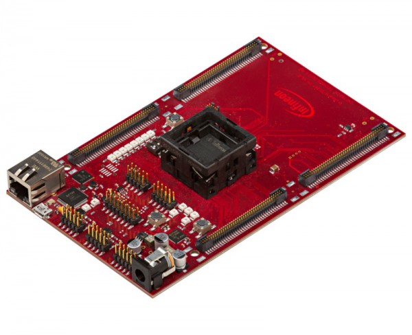
- Order number: 37.96.0429.0
- Open text field 1: KIT_A2G_TC397_5V_TRB_S,A2G,TRB,TC3x7,TC397
- Open text field 2: SP004330576
KIT_A2G_TC397_5V_TRB_S
Description:
The User Manual provide information about using, configuration and connecting the TriBoard with Infineon AURIX™ TC3X7 device. The manual provide information for different hardware types. There exist different hardware with Through Hole socket (TriBoard TC3X7 TH) and soldered devices (TriBoard TC3X7). The schematic is identically for the all boards if not other mentioned in chapter schematic. The placing on the boards is slightly different around the TC3X7 itself dependent of the space (socket need more space and has through hole), but the most components are on the same location. All figures are valid for each board if not differently mentioned.
Summary of Features:
• Infineon’s TC3X7 (TC397) AURIX™ 2G Controller B-Step in LFBGA-292 Package, socketed
• FlexRay™ 1) Transceivers
• High Speed CAN Transceivers (CAN-FD capable)
• USB to UART bridge
• Ethernet Gigabit PHY
• Serial Eeprom
• LIN Transceiver
• Crystal 20MHz (default) or External Clock
• USB miniWiggler JDS for easy debugging
• 8 Low Power Status LEDs
• 8-DIP switches for configuration
• access to all pins of controller
• 00mm x 160mm (EURO-Board)
Connectors
The TC3X7 TriBoard offers a wide variety of connectors:
• Standard power connector
• Micro USB connector for ASC Interface (ASC0) and miniWiggler
• RJ45 connector for Ethernet
• 16-pin header for JTAG interface (OCDS)
• 2 x 10-pin header for DAP and DAPE (DAPE only usable on Emulation Device)
• 10pin (2x5) Header for LIN Transceiver (LIN)
• 2 x 10pin (2x5) Header for CAN High Speed Transceiver (CAN0 and CAN1)
• 2 x 10pin (2x5) Header for FlexRay™ (ERAY-A and ERAY-B)
• four 80-pin connectors (male) + four 80-pin connectors (female) with all I/O signals
• optional ETK connector
• optional 6pin (IEEE1394) Socket for HSCT
• optional Aurora connector (only with Emulation Device)
Components
• Infineon’s Multi Voltage Safety Micro Processor Supply TLF35584QV
• Three LEDs to validate power supply (5Volt / 3,3 Volt / 1,25 Volt)
• LED indicating safe state signal 2 from TLF35584
• LED indicating /HDRST (ESR0) active state
• LED indicating activ miniWiggler JDS
• LED switched via DAS software
• 2 x Infineon’s FlexRay™ Transceiver TLE9221SX
• 2 x Infineon’s High Speed CAN-Transceiver TLE9251VSJ
• Infineon’s LIN-Transceiver TLE 7259-3GE
• USB to UART bridge FT2232HL (FTDI)
• Single Port Gigabit Ethernet PHY PEF7071 (LANTIQ)
• 8 general purpose LEDs
Features
• 2K I 2C Serial Eeprom with EUI-48™ 1) Node Identity (MICROCHIP)
• Reset switch
• Enable switch
• Generic switch
• 4-pin Dip switch
Target Applications:
• Automotive
• Sensor Fusion
• Chassis
• eVehicles
• Powertrain
• Industrial


